SNR vs BER plot
Thursday 24 March 2011
Wednesday 23 March 2011
More On DSP Kit TMS320c6710
Introduction
This module describes the TMS320C6713 DSK development board and how to use it in a Code Composer Studio (CCS) v3.3 project that uses DSP/BIOS. An example project is included.
Reading
- TMS320C6713 DSK Technical Reference
- SLWS106D: TLV320AIC23 Technical Manual
- SPRA677: A DSP/BIOS AIC23 Codec Device Driver for the TMS320C6713 DSK
- SPRU616: DSP/BIOS Driver Developer's Guide
- SPRA846: A DSP/BIOS EDMA McBSP Device Driver for TMS320C6x1x DSPs
DSK Hardware
The following figure shows the block diagram of the TMS320C6713 DSK hardware. The heart of the DSK is the TMS320C6713 DSP chip which runs at 225 MHz. The DSP is in the center of the block diagram and connects to external memory through the EMIF interface. There are several devices connected to this interface. One device is a 16 Mbyte SDRAM chip. This memory, along with the internal DSP memory, will be where code and data are stored.
On the DSK board there is a TLV320AIC23 (AIC23) 16-bit stereo audio CODEC (coder/decoder). The chip has a mono microphone input, stereo line input, stereo line output and stereo headphone output. These outputs are accessible on the DSK board. The AIC23 figure shows a simplified block diagram of the AIC23 and its interfaces. The CODEC interfaces to the DSP through its McBSP serial interface. The CODEC is a 16-bit device and will be set up to deliver 16-bit signed 2's complement samples packed into a 32-bit word. Each 32-bit word will contain a sample from the left and right channel in that order -32768 to 32767.
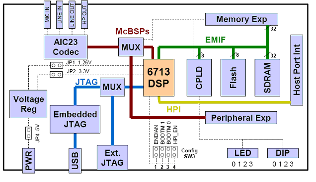
Figure 1: TMS320C613 DSK Block Diagram taken from TMS320C6713 DSK Technical Reference

Figure 2: Simplified AIC23 CODEC Interface taken from TMS320C6713 DSK Technical Reference
DSK6713 Audio Project Framework
The following figure shows a diagram of the software that will be used in this module. Texas Instruments has written some drivers for the McBSP that get data from the AIC23 and write data to the AIC23. The input data is put into an input stream (input buffer) and the output data is read from an output stream (output buffer). The signal processing software simply needs to get a buffer from the input stream, process the data, then put the resulting buffer in the output stream.
The project is set up using DSP/BIOS, a real time operating systems developed by TI. This module does not explain how to use DSP/BIOS but it will explain what objects are used in this project. The main objects are an input stream,
inStream, an output stream, outStream, and a task, TSK_processing, which uses the function processing().
Microcontroller
A microcontroller (sometimes abbreviated µC, uC or MCU) is a small computer on a single integrated circuit containing a processor core, memory, and programmable input/output peripherals. Program memory in the form of NOR flash or OTP ROM is also often included on chip, as well as a typically small amount of RAM. Microcontrollers are designed for embedded applications, in contrast to the microprocessors used in personal computers or other general purpose applications.
Microcontrollers are used in automatically controlled products and devices, such as automobile engine control systems, implantable medical devices, remote controls, office machines, appliances, power tools, and toys. By reducing the size and cost compared to a design that uses a separate microprocessor, memory, and input/output devices, microcontrollers make it economical to digitally control even more devices and processes. Mixed signal microcontrollers are common, integrating analog components needed to control non-digital electronic systems.
Some microcontrollers may use four-bit words and operate at clock rate frequencies as low as 4 kHz, for low power consumption (milliwatts or microwatts). They will generally have the ability to retain functionality while waiting for an event such as a button press or other interrupt; power consumption while sleeping (CPU clock and most peripherals off) may be just nanowatts, making many of them well suited for long lasting battery applications. Other microcontrollers may serve performance-critical roles, where they may need to act more like a digital signal processor (DSP), with higher clock speeds and power consumption.
Diversity Scheme In Telecommunication
In telecommunications, a diversity scheme refers to a method for improving the reliability of a message signal by using two or more communication channels with different characteristics. Diversity plays an important role in combatting fading and co-channel interference and avoiding error bursts. It is based on the fact that individual channels experience different levels of fading and interference. Multiple versions of the same signal may be transmitted and/or received and combined in the receiver. Alternatively, a redundant forward error correction code may be added and different parts of the message transmitted over different channels. Diversity techniques may exploit the multipath propagation, resulting in a diversity gain, often measured in decibels.
 The following classes of diversity schemes can be identified:
http://en.wikipedia.org/wiki/File:Space_diversity.gif

- Time diversity: Multiple versions of the same signal are transmitted at different time instants. Alternatively, a redundant forward error correction code is added and the message is spread in time by means of bit-interleaving before it is transmitted. Thus, error bursts are avoided, which simplifies the error correction.
- Frequency diversity: The signal is transmitted using several frequency channels or spread over a wide spectrum that is affected by frequency-selective fading. Middle-late 20th century microwave radio relay lines often used several regular wideband radio channels, and one protection channel for automatic use by any faded channel. Later examples include:
- OFDM modulation in combination with subcarrier interleaving and forward error correction
- Spread spectrum, for example frequency hopping or DS-CDMA.
- Space diversity: The signal is transmitted over several different propagation paths. In the case of wired transmission, this can be achieved by transmitting via multiple wires. In the case of wireless transmission, it can be achieved by antenna diversity using multiple transmitter antennas (transmit diversity) and/or multiple receiving antennas (reception diversity). In the latter case, a diversity combining technique is applied before further signal processing takes place. If the antennas are far apart, for example at different cellular base station sites or WLAN access points, this is called macrodiversity or site diversity. If the antennas are at a distance in the order of one wavelength, this is called microdiversity. A special case is phased antenna arrays, which also can be used for beamforming, MIMO channels and Space–time coding (STC).
- Polarization diversity: Multiple versions of a signal are transmitted and received via antennas with different polarization. A diversity combining technique is applied on the receiver side.
- Multiuser diversity: Multiuser diversity is obtained by opportunistic user scheduling at either the transmitter or the receiver. Opportunistic user scheduling is as follows: the transmit selects the best user among candidate receivers according to the qualities of each channel between the transmitter and each receiver. In FDD systems, a receiver must feed back the channel quality information to the transmitter with the limited level of resolution.
- Cooperative diversity: Achieves antenna diversity gain by using the cooperation of distributed antennas belonging to each node.
http://en.wikipedia.org/wiki/File:Space_diversity.gif
Antenna diversity/space diversity
Antenna diversity, also known as space diversity, is any one of several wireless diversity schemes that use two or more antennas to improve the quality and reliability of a wireless link. Often, especially in urban and indoor environments, there is no clear line-of-sight (LOS) between transmitter and receiver. Instead the signal is reflected along multiple paths before finally being received. Each of these bounces can introduce phase shifts, time delays, attenuations, and distortions that can destructively interfere with one another at the aperture of the receiving antenna. Antenna diversity is especially effective at mitigating these multipath situations. This is because multiple antennas offer a receiver several observations of the same signal. Each antenna will experience a different interference environment. Thus, if one antenna is experiencing a deep fade, it is likely that another has a sufficient signal. Collectively such a system can provide a robust link. While this is primarily seen in receiving systems (diversity reception), the analog has also proven valuable for transmitting systems (transmit diversity) as well.
 Inherently an antenna diversity scheme requires additional hardware and integration versus a single antenna system but due to the commonality of the signal paths a fair amount of circuitry can be shared. Also with the multiple signals there is a greater processing demand placed on the receiver, which can lead to tighter design requirements. Typically, however, signal reliability is paramount and using multiple antennas is an effective way to decrease the number of drop-outs and lost connections.
Antenna Techniques
Antenna diversity can be realized in several ways. Depending on the environment and the expected interference, designers can employ one or more of these methods to improve signal quality. In fact multiple methods are frequently used to further increase reliability.
- Switching – In a switching receiver, the signal from only one antenna is fed to the receiver for as long as the quality of that signal remains above some prescribed threshold. If and when the signal degrades, another antenna is switched in. Switching is the easiest and least power consuming of the antenna diversity processing techniques but periods of fading and desynchronization may occur while the quality of one antenna degrades and another antenna link is established.
- Selecting – As with switching, selection processing presents only one antenna’s signal to the receiver at any given time. The antenna chosen, however, is based on the best signal-to-noise ratio (SNR) among the received signals. This requires that a pre-measurement take place and that all antennas have established connections (at least during the SNR measurement) leading to a higher power requirement. The actual selection process can take place in between received packets of information. This ensures that a single antenna connection is maintained as much as possible. Switching can then take place on a packet-by-packet basis if necessary.
- Combining – In combining, all antennas maintain established connections at all times. The signals are then combined and presented to the receiver. Depending on the sophistication of the system, the signals can be added directly (equal gain combining) or weighted and added coherently (maximal-ratio combining). Such a system provides the greatest resistance to fading but since all the receive paths must remain energized, it is also consumes the most power.
- Dynamic Control – Dynamically controlled receivers are capable of choosing from the above processing schemes for whenever the situation arises. While much more complex, they optimize the power vs. performance trade-off. Transitions between modes and/or antenna connections are signaled by a change in the perceived quality of the link. In situations of low fading, the receiver can employ no diversity and use the signal presented by a single antenna. As conditions degrade, the receiver can then assume the more highly reliable but power-hungry modes described above.
Another common usage is in Wi-Fi networking gear and cordless telephones to compensate for multipath interference. The base station will switch reception to one of two antennas depending on which is currently receiving a stronger signal. For best results, the antennas are usually placed one wavelength apart. For microwave bands, where the wavelengths are under 100 cm, this can often be done with two antennas attached to the same hardware. For lower frequencies and longer wavelengths, the antennas must be several meters apart, making it much less reasonable.
Mobile phone towers also often take advantage of diversity - each face of a tower will often have three antennas; one is transmitting, while the other two perform diversity reception.
The use of multiple antennas at both transmit and receive results in a multiple-input multiple-output (MIMO) system. The use of diversity techniques at both ends of the link is termed space–time coding.
Refrences:
http://en.wikipedia.org/wiki/Antenna_diversity
Antenna Techniques
Antenna diversity can be realized in several ways. Depending on the environment and the expected interference, designers can employ one or more of these methods to improve signal quality. In fact multiple methods are frequently used to further increase reliability.
Types Of Diversity
Spatial Diversity
Spatial diversity employs multiple antennas, usually with the same characteristics, that are physically separated from one another. Depending upon the expected incidence of the incoming signal, sometimes a space on the order of a wavelength is sufficient. Other times much larger distances are needed. Cellularization or sectorization, for example, is a spatial diversity scheme that can have antennas or base stations miles apart. This is especially beneficial for the mobile communication industry since it allows multiple users to share a limited communication spectrum and avoid co-channel interference.Pattern Diversity
Pattern diversity consists of two or more co-located antennas with different radiation patterns. This type of diversity makes use of directive antennas that are usually physically separated by some (often short) distance. Collectively they are capable of discriminating a large portion of angle space and can provide a higher gain versus a single omnidirectional radiator.Polarization Diversity
Polarization diversity combines pairs of antennas with orthogonal polarizations (i.e. horizontal/vertical, ± slant 45°, Left-hand/Right-hand CP etc). Reflected signals can undergo polarization changes depending on the medium through which they are travelling. A polarisation difference of 90° will result in an attenuation factor of up to 34dB in signal strength. By pairing two complementary polarizations, this scheme can immunize a system from polarization mismatches that would otherwise cause signal fade. Additionally, such diversity has proven valuable at radio and mobile communication base stations since it is less susceptible to the near random orientations of transmitting antennas.Transmit/Receive Diversity
Transmit/Receive diversity uses two separate, collocated antennas for transmit and receive functions. Such a configuration eliminates the need for a duplexer and can protect sensitive receiver components from the high power used in transmit.Adaptive Arrays
Adaptive arrays can be a single antenna with active elements or an array of similar antennas with ability to change their combined radiation pattern as different conditions persist. Active electronically scanned arrays (AESAs) manipulate phase shifters and attenuators at the face of each radiating site to provide a near instantaneous scan ability as well as pattern and polarization control. This is especially beneficial for radar applications since it affords a signal antenna the ability to switch among several different modes such as searching, tracking, mapping and jamming countermeasures.Processing Techniques
All of the above techniques require some sort of post processing to recover the desired message. Among these techniques are:- Switching – In a switching receiver, the signal from only one antenna is fed to the receiver for as long as the quality of that signal remains above some prescribed threshold. If and when the signal degrades, another antenna is switched in. Switching is the easiest and least power consuming of the antenna diversity processing techniques but periods of fading and desynchronization may occur while the quality of one antenna degrades and another antenna link is established.
- Selecting – As with switching, selection processing presents only one antenna’s signal to the receiver at any given time. The antenna chosen, however, is based on the best signal-to-noise ratio (SNR) among the received signals. This requires that a pre-measurement take place and that all antennas have established connections (at least during the SNR measurement) leading to a higher power requirement. The actual selection process can take place in between received packets of information. This ensures that a single antenna connection is maintained as much as possible. Switching can then take place on a packet-by-packet basis if necessary.
- Combining – In combining, all antennas maintain established connections at all times. The signals are then combined and presented to the receiver. Depending on the sophistication of the system, the signals can be added directly (equal gain combining) or weighted and added coherently (maximal-ratio combining). Such a system provides the greatest resistance to fading but since all the receive paths must remain energized, it is also consumes the most power.
- Dynamic Control – Dynamically controlled receivers are capable of choosing from the above processing schemes for whenever the situation arises. While much more complex, they optimize the power vs. performance trade-off. Transitions between modes and/or antenna connections are signaled by a change in the perceived quality of the link. In situations of low fading, the receiver can employ no diversity and use the signal presented by a single antenna. As conditions degrade, the receiver can then assume the more highly reliable but power-hungry modes described above.
Applications
A well-known practical application of diversity reception is in wireless microphones, and in similar electronic devices such as wireless guitar systems. A wireless microphone with a non-diversity receiver (a receiver having only one antenna) is prone to random drop-outs, fades, noise, or other interference, especially if the transmitter (the wireless microphone) is in motion. A wireless microphone or sound system using diversity reception will switch to the other antenna within microseconds if one antenna experiences noise, providing an improved quality signal with fewer drop-outs and noise. Ideally, no drop-outs or noise will occur in the received signal.Another common usage is in Wi-Fi networking gear and cordless telephones to compensate for multipath interference. The base station will switch reception to one of two antennas depending on which is currently receiving a stronger signal. For best results, the antennas are usually placed one wavelength apart. For microwave bands, where the wavelengths are under 100 cm, this can often be done with two antennas attached to the same hardware. For lower frequencies and longer wavelengths, the antennas must be several meters apart, making it much less reasonable.
Mobile phone towers also often take advantage of diversity - each face of a tower will often have three antennas; one is transmitting, while the other two perform diversity reception.
The use of multiple antennas at both transmit and receive results in a multiple-input multiple-output (MIMO) system. The use of diversity techniques at both ends of the link is termed space–time coding.
Antenna diversity for MIMO
Diversity Coding is the spatial coding techniques for a MIMO system in wireless channels. Wireless channels severely suffer from fading phenomena, which causes unreliability in data decoding. Fundamentally, diversity coding sends multiple copies through multiple transmit antennas, so as to improve the reliability of the data reception. If one of them fails to receive, the others are used for data decoding.Refrences:
http://en.wikipedia.org/wiki/Antenna_diversity
Tuesday 22 March 2011
DSP KIT
The device use to enhance and implement the algorithms related to signals processing and communication......
DSP KIT
 The TMS320C6713 DSP Starter Kit (DSK) developed jointly with Spectrum Digital is a low-cost development platform designed to speed the development of high precision applications based on TI´s TMS320C6000 floating point DSP generation. The kit uses USB communications for true plug-and-play functionality. Both experienced and novice designers can get started immediately with innovative product designs with the DSK´s full featured Code Composer Studio™ IDE and eXpressDSP™ Software which includes DSP/BIOS and Reference Frameworks.
The C6713 DSK tools includes the latest fast simulators from TI and access to the Analysis Toolkit via Update Advisor which features the Cache Analysis tool and Multi-Event Profiler. Using Cache Analysis developers improve the performance of their application by optimizing cache usage. By providing a graphical view of the on-chip cache activity over time the user can quickly determine if their code is using the on-chip cache to get peak performance.
The C6713 DSK allows you to download and step through code quickly and uses Real Time Data Exchange (RTDX™) for improved Host and Target communications. The DSK includes the Fast Run Time Support libraries and utilities such as Flashburn to program flash, Update Advisor to download tools, utilities and software and a power on self test and diagnostic utility to ensure the DSK is operating correctly.
The full contents of the kit include:
US
DSP KIT
The C6713 DSK tools includes the latest fast simulators from TI and access to the Analysis Toolkit via Update Advisor which features the Cache Analysis tool and Multi-Event Profiler. Using Cache Analysis developers improve the performance of their application by optimizing cache usage. By providing a graphical view of the on-chip cache activity over time the user can quickly determine if their code is using the on-chip cache to get peak performance.
The C6713 DSK allows you to download and step through code quickly and uses Real Time Data Exchange (RTDX™) for improved Host and Target communications. The DSK includes the Fast Run Time Support libraries and utilities such as Flashburn to program flash, Update Advisor to download tools, utilities and software and a power on self test and diagnostic utility to ensure the DSK is operating correctly.
· C6713 DSP Development Board with 512K Flash and 16MB SDRAM
· C6713 DSK Code Composer Studio™ IDE including the Fast Simulators and access to Analysis Toolkit on Update Advisor
· Quick Start Guide
· Technical Reference
· Customer Support Guide
· USB Cable
· Universal Power Supply
· AC Power Cord(s)
· MATLAB from The Mathworks 30 day free evaluation
Ordering Information: TMDSDSK6713 includes a standard Features
The DSK features the TMS320C6713 DSP, a 225 MHz device delivering up to 1800 million instructions per second (MIPs) and 1350 MFLOPS. This DSP generation is designed for applications that require high precision accuracy. The C6713 is based on the TMS320C6000 DSP platform designed to needs of high-performing high-precision applications such as pro-audio, medical and diagnostic. Other hardware features of the TMS320C6713 DSK board include:· Embedded JTAG support via USB
· High-quality 24-bit stereo codec
· Four 3.5mm audio jacks for microphone, line in, speaker and line out
· 512K words of Flash and 16 MB SDRAM
· Expansion port connector for plug-in modules
· On-board standard IEEE JTAG interface
· +5V universal power supply
Software - Designers can readily target the TMS32C6713 DSP through TI´s robust and comprehensive Code Composer Studio™ DSK development platform. The tools, which run on Windows© 98, Windows 2000 and Windows XP, allow developers to seamlessly manage projects of any complexity. Code Composer Studio features for the TMS320C6713 DSK include:· A complete Integrated Development Environment (IDE), an efficient optimizing C/C++ compiler assembler, linker, debugger, an a advanced editor with Code Maestro™ technology for faster code creation, data visualization, a profiler and a flexible project manager
· DSP/BIOS™ real-time kernel
· Target error recovery software
· DSK diagnostic tool
· "Plug-in" ability for third-party software for additional functionality
Alternative Tools / Software:
Code Composer Studio (CCStudio) Integrated Development Environment (IDE) v4.x
Wireless MIMO Systems
In radio, multiple-input and multiple-output, or MIMO (commonly pronounced my-moh or me-moh), is the use of multiple antennas at both the transmitter and receiver to improve communication performance. It is one of several forms of smart antenna technology. Note that the terms input and output refer to the radio channel carrying the signal, not to the devices having antennas.
MIMO technology has attracted attention in wireless communications, because it offers significant increases in data throughput and link range without additional bandwidth or transmit power. It achieves this by higher spectral efficiency (more bits per second per hertz of bandwidth) and link reliability or diversity (reduced fading). Because of these properties, MIMO is an important part of modern wireless communication standards such as IEEE 802.11n (Wifi), 4G, 3GPP Long Term Evolution, WiMAX and HSPA+.
Introduction
Wireless operations permits services, such as long range communications, that are impossible or impractical to implement with the use of wires. The term is commonly used in the telecommunications industry to refer to telecommunications systems (e.g. radio transmitters and receivers, remote controls, computer networks, network terminals, etc.) which use some form of energy (e.g. radio frequency (RF), infrared light, laser light, visible light, acoustic energy, etc.) to transfer information without the use of wires. Information is transferred in this manner over both short and long distances.
refrences:
http://en.wikipedia.org/wiki/MIMO
MIMO technology has attracted attention in wireless communications, because it offers significant increases in data throughput and link range without additional bandwidth or transmit power. It achieves this by higher spectral efficiency (more bits per second per hertz of bandwidth) and link reliability or diversity (reduced fading). Because of these properties, MIMO is an important part of modern wireless communication standards such as IEEE 802.11n (Wifi), 4G, 3GPP Long Term Evolution, WiMAX and HSPA+.
Introduction
refrences:
http://en.wikipedia.org/wiki/MIMO
Subscribe to:
Posts (Atom)